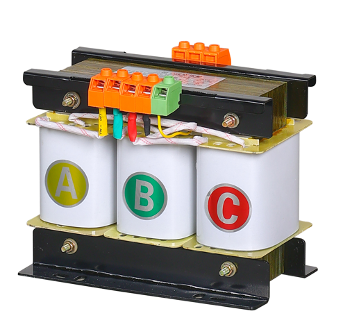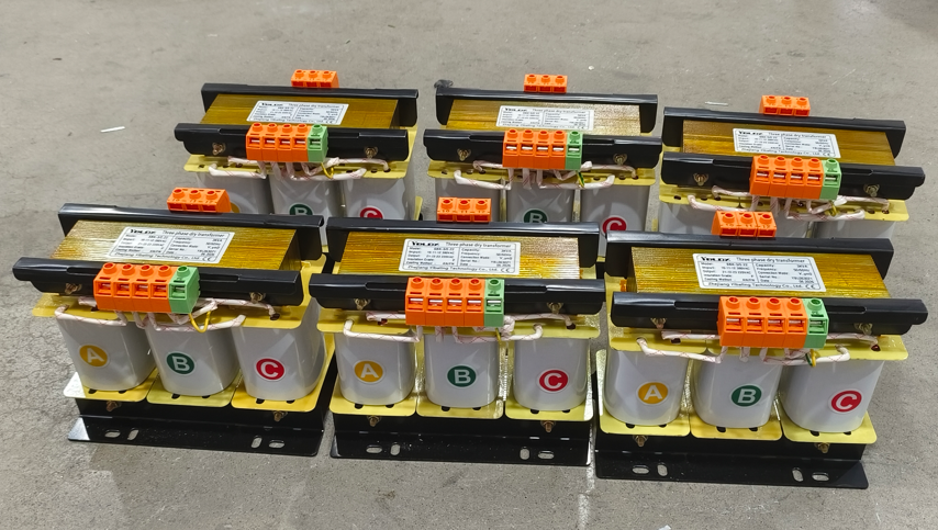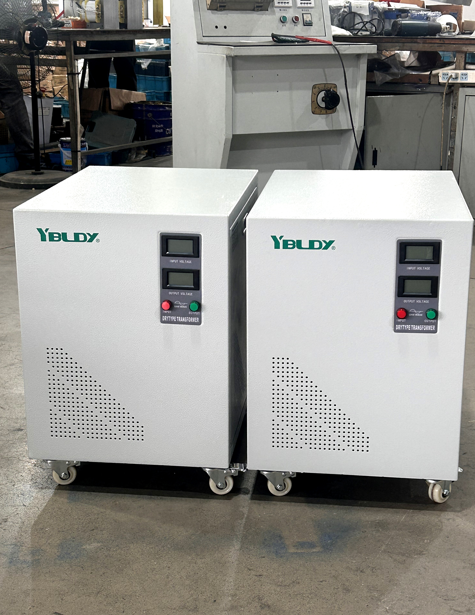

Why can ZBK be used for direct current?
In industrial settings, many devices do not directly consume alternating current – they require direct current.
Motor speed control, electroplating, electrolysis, charging, electromagnets, direct welding machines... The front end of these devices almost invariably includes one component: rectification.
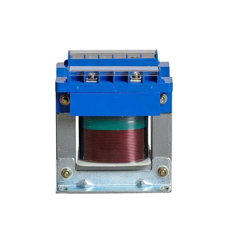
And at the front end of the rectification circuit, there is often a device that is not particularly prominent but is absolutely indispensable –The ZBK rectifier single-phase transformer.
What is the ZBK control transformer for?
The ZBK control transformer is not an ordinary transformer.
The task of an ordinary transformer is: input 220V, output 220V (or 110V, 36V, etc.), thevoltage changes, but the waveform remains the same – still alternating current.
The task of the ZBK control transformer is: to supply power to the rectification circuit.
The voltage it outputs will be connected to rectification diodes, thyristors or rectifier bridges, ultimately becoming direct current. Therefore, in its design, the ZBK control transformer specifically takes into account the characteristics of the rectification circuit:
The output is not for direct use by resistors or motors, but for rectifier tubes.
It has to withstand the current pulsation and harmonics brought by rectification.
Insulation, temperature rise, and structure must all match the rectification conditions.
In one sentence: The ZBK control transformer is the "preliminary rectification power supply" section, changing voltage is just its surface work, adapting to rectification is its professional field.
Where are ZBK control transformers needed?
| Application Scenario | Specific Use | Why Choose a ZBK Control Transformer |
| Electroplating & Electrolysis | Electroplating tanks, electrolysis power supplies | Requires high-current, low-voltage DC; precise voltage matching before rectification is essential |
| Electromagnets | Lifting electromagnets, magnetic chucks | DC-powered; transformer must adapt to pulsed current after rectification |
| DC Motor Speed Control | Small DC motors, machine tool feed systems | Front end of rectified power supplies; provides voltage matching and electrical isolation |
| Laboratory Power Supplies | Adjustable DC regulated power supplies | A core component of rectifier systems |
| Excitation Devices | Generator excitation, synchronous motor excitation | Supplies AC power for thyristor rectification |
Simply put: Anywhere AC is converted to DC, a rectifier transformer is almost always required at the front end.
ZBK Control Transformer vs. Ordinary Transformer
| Comparison Item | Ordinary Single-Phase Transformer | ZBK Control Transformer (Rectifier Transformer) |
| Backend Load | Resistors, motors, lighting | Rectifier tubes + DC loads |
| Current Waveform | Sinusoidal | Pulsating DC (non-sinusoidal) |
| Design Priority | Voltage accuracy | Withstanding harmonics and pulsating current |
| Insulation Requirements | Standard | Higher (resists pulse voltage and reverse recovery spikes) |
| Temperature Rise Margin | Standard | Larger (rectification generates more heat) |
| Application Scenarios | General use | Dedicated to rectified power supplies |
Ordinary transformers can technically be used for rectification, but they tend to overheat and age quickly. ZBK control transformers are built specifically for this tougher job.
Looks similar, but it's different where it matters
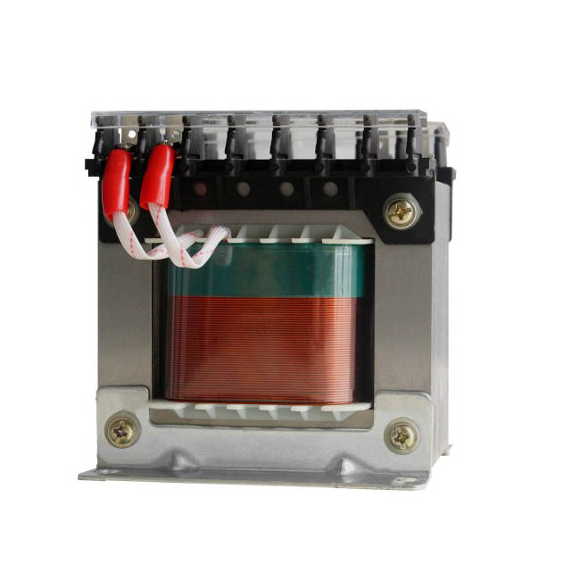
At first glance, a ZBK looks a lot like a standard BK transformer. But inside, we’ve made several changes to handle rectification duty properly:
Winding design – We take into account the DC component that comes with rectified current. This prevents the core from saturating unevenly, which would cause extra heat and noise.
Insulation class – Typically Class F (155°C) or Class H (180°C). Simply put, it handles heat better.
Voltage regulation – Rectified loads can swing quite a bit. The ZBK is designed to keep the output stable even when the load changes suddenly.
Surge resistance – When a rectifier tube or diode fires, there’s a sharp inrush current. The ZBK can take that hit without complaint.
Tap design – Multiple taps let you fine tune the voltage to match different rectification setups (half wave, full wave, bridge, etc.).
We also use good materials: pure copper windings, high grade silicon steel, and vacuum impregnation. It’s not “just enough”. It’s built to run for years in rectifier duty.
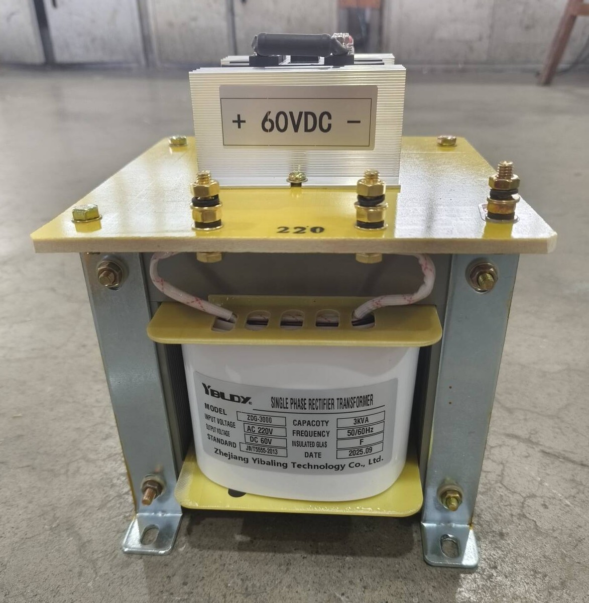
Things to watch when choosing a ZBK
Capacity – Figure out the DC power you need after rectification, then divide by efficiency to get the AC-side VA. Then add at least 20-30% extra as a safety margin.
Output voltage – Remember that diodes and thyristors drop some voltage (about 0.7-1V for diodes, more for thyristors). Your transformer output should be a bit higher than the final DC voltage you want.
Rectification method – Half-wave, full-wave, and bridge rectification each put different demands on the transformer. Tell us what you’re using.
Multi-tap or not – If you need to adjust the DC voltage regularly, get a multi-tap or an adjustable model.
Insulation class – Rectification runs hot. Go with Class F or H for peace of mind.
A Real-World Example
An environmental equipment manufacturer produced electroplating power supplies with the following setup:Single-phase 220V input → Transformer → Rectifier bridge → Low-voltage, high-current output to electroplating tanks.
They initially used ordinary control transformers. Within a year, the transformers overheated, produced excessive noise, and suffered insulation aging.
After switching to ZBK rectifier transformers of the same capacity:
Operating temperature dropped by nearly 15°C.
No issues occurred during two years of continuous operation.
Related News
- What ZSG Three-Phase Dry-Type Rectifier Transformer work?
- Which one is good S13 Oil-Immersed Distribution Transformer?
- How to choose JBK5 Machine Tool Control Transformer?
- How BK Machine Tool Transformer 220V works?
- Which one is good SBK Three-Phase Dry-Type Transformer?
- How to choose SBW Intelligent Servo Voltage Stabilizer?
Leave me a message